2 Basic Concepts
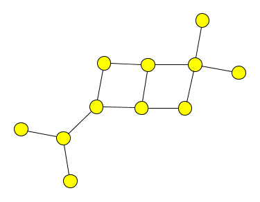
The purpose of a GraphML document is to define a graph. Let us start by considering the graph shown in the figure below. It contains 11 nodes and 12 edges.
2.1 A Simple Graph
The graph is contained in the file
simple.graphml:
<?xml version="1.0" encoding="UTF-8"?>
<graphml xmlns="http://graphml.graphdrawing.org/xmlns"
    xmlns:xsi="http://www.w3.org/2001/XMLSchema-instance"
    xsi:schemaLocation="http://graphml.graphdrawing.org/xmlns
     http://graphml.graphdrawing.org/xmlns/1.0/graphml.xsd">
  <graph id="G" edgedefault="undirected">
    <node id="n0"/>
    <node id="n1"/>
    <node id="n2"/>
    <node id="n3"/>
    <node id="n4"/>
    <node id="n5"/>
    <node id="n6"/>
    <node id="n7"/>
    <node id="n8"/>
    <node id="n9"/>
    <node id="n10"/>
    <edge source="n0" target="n2"/>
    <edge source="n1" target="n2"/>
    <edge source="n2" target="n3"/>
    <edge source="n3" target="n5"/>
    <edge source="n3" target="n4"/>
    <edge source="n4" target="n6"/>
    <edge source="n6" target="n5"/>
    <edge source="n5" target="n7"/>
    <edge source="n6" target="n8"/>
    <edge source="n8" target="n7"/>
    <edge source="n8" target="n9"/>
    <edge source="n8" target="n10"/>
  </graph>
</graphml>
The GraphML document consists of a graphml element and a variety of subelements: graph, node, edge.
In the remainder of this section we will discuss these elements in detail and show how they define a graph.
2.2 The Header
In this section we discuss the parts of the document which are common to all GraphML documents, basically the graphml element.
<?xml version="1.0" encoding="UTF-8"?>
<graphml xmlns="http://graphml.graphdrawing.org/xmlns"
    xmlns:xsi="http://www.w3.org/2001/XMLSchema-instance"
    xsi:schemaLocation="http://graphml.graphdrawing.org/xmlns
     http://graphml.graphdrawing.org/xmlns/1.0/graphml.xsd">

  ...

</graphml>
The first line of the document is an XML process instruction which defines that the document adheres to the XML 1.0 standard and that the encoding of the document is UTF-8, the standard encoding for XML documents. Of course other encodings can be chosen for GraphML documents.
The second line contains the root-element element of a GraphML document: the graphml element.
The graphml element, like all other GraphML elements, belongs to the namespace
http://graphml.graphdrawing.org/xmlns.
For this reason we define this namespace as the default namespace in the document by adding the XML Attribute
xmlns="http://graphml.graphdrawing.org/xmlns" to it.
The two other XML Attributes are needed to specify the XML Schema for this document. In our example we use the standard schema for GraphML documents located on the graphdrawing.org server.
The first attribute, xmlns:xsi="http://www.w3.org/2001/XMLSchema-instance", defines xsi as the XML Schema namespace.
The second attribute, xsi:schemaLocation="http://graphml.graphdrawing.org/xmlns
http://graphml.graphdrawing.org/xmlns/1.0/graphml.xsd"
, defines the XML Schema location for all elements in the GraphML namespace.
The XML Schema reference is not required but it provides means to validate the document and is therefore strongly recommended.
2.3 The Graph
A graph is, not surprisingly, denoted by a graph
element. Nested inside a graph element
are the declarations of nodes and edges.
A node is declared with a node element,
and an egde with an edge element.
<graph id="G" edgedefault="directed">
<node id="n0"/>
<node id="n1"/>
...
<node id="n10"/>
<edge source="n0" target="n2"/>
<edge source="n1" target="n2"/>
...
<edge source="n8" target="n10"/>
</graph>
In GraphML there is no order defined for the appearance of
node and edge elements.
Therefore the following example is a perfectly valid GraphML fragment:
<graph id="G" edgedefault="directed">
<node id="n0"/>
<edge source="n0" target="n2"/>
<node id="n1"/>
<node id="n2"/>
...
</graph>
2.3.1 Declaring a Graph
Graphs in GraphML are mixed, in other words, they can contain directed and undirected edges at the same time. If no direction is specified when an edge is declared, the default direction is applied to the edge.
The default direction is declared as the XML Attribute edgedefault of the graph element. The two possible value for this XML Attribute are directed and undirected.
Note that the default direction must be specified.
Optionally an identifier for the graph can be specified with the XML Attribute id. The identifier is used, when it is necessary to reference the graph.
2.3.2 Declaring a Node
Nodes in the graph are declared by thenode element.
Each node has an identifier, which must be unique within
the entire document, i.e., in a document there must be no two nodes
with the same identifier.
The identifier of a node is defined by the XML-Attribute
id.
2.3.3 Declaring an Edge
Edges in the graph are declared by the edge element.
Each edge must define its two endpoints with the XML-Attributes
source and target.
The value of the source, resp. target,
must be the identifier of a node in the same document.
Edges with only one endpoint, also called loops, selfloops, or
reflexive edges, are defined by having the same value for
source and target.
The optional XML-Attribute directed declares if the edge is directed or undirected. The value true declares a directed edge, the value false an undirected edge. If the direction is not explicitely defined, the default direction is applied to this edge as defined in the enclosing graph.
Optionally an identifier for the edge can be specified with the XML Attribute id.
When it is necessary to reference the edge, the id XML-Attribute is used.
...
<edge id="e1" directed="true" source="n0" target="n2"/>
...
2.4 GraphML-Attributes
In the previous section we discussed how to describe the topology of a graph in GraphML. While pure topological information may be sufficient for some appications of GraphML, for the most time additional information is needed. With the help of the extension GraphML-Attributes one can specify additional information of simple type for the elements of the graph. Simple type means that the information is restricted to scalar values, e.g. numerical values and strings.
If you want to add structured content to graph elements you should use the key/data extension mechanism of GraphML. For a detailed description of this mechanism see Chapter 4. GraphML-Attributes themselfes are specialized data/key extensions.
GraphML-Attributes must not be confounded with XML-Attributes which are a different concept.
2.4.1 GraphML-Attributes Example
In this section a graph with colored nodes and edge weights will be our running example.
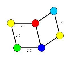
We will use GraphML-Attributes to store the extra data on the nodes and edges. The file attributes.graphml shows the result:
<?xml version="1.0" encoding="UTF-8"?>
<graphml xmlns="http://graphml.graphdrawing.org/xmlns"
xmlns:xsi="http://www.w3.org/2001/XMLSchema-instance"
xsi:schemaLocation="http://graphml.graphdrawing.org/xmlns
http://graphml.graphdrawing.org/xmlns/1.0/graphml.xsd">
<key id="d0" for="node" attr.name="color" attr.type="string">
<default>yellow</default>
</key>
<key id="d1" for="edge" attr.name="weight" attr.type="double"/>
<graph id="G" edgedefault="undirected">
<node id="n0">
<data key="d0">green</data>
</node>
<node id="n1"/>
<node id="n2">
<data key="d0">blue</data>
</node>
<node id="n3">
<data key="d0">red</data>
</node>
<node id="n4"/>
<node id="n5">
<data key="d0">turquoise</data>
</node>
<edge id="e0" source="n0" target="n2">
<data key="d1">1.0</data>
</edge>
<edge id="e1" source="n0" target="n1">
<data key="d1">1.0</data>
</edge>
<edge id="e2" source="n1" target="n3">
<data key="d1">2.0</data>
</edge>
<edge id="e3" source="n3" target="n2"/>
<edge id="e4" source="n2" target="n4"/>
<edge id="e5" source="n3" target="n5"/>
<edge id="e6" source="n5" target="n4">
<data key="d1">1.1</data>
</edge>
</graph>
</graphml>
2.4.2 Declaring GraphML-Attributes
A GraphML-Attribute is defined by a key element which specifies the identifier, name, type and domain of the attribute.
The identifier is specified by the XML-Attribute id and is used to refer to the GraphML-Attribute inside the document.
The name of the GraphML-Attribute is defined by the XML-Attribute attr.name and must be unique among all GraphML-Attributes declared in the document. The purpose of the name is that applications can identify the meaning of the attribute. Note that the name of the GraphML-Attribute is not used inside the document, the identifier is used for this purpose.
The type of the GraphML-Attribute can be either
boolean, int, long, float, double, or string.
These types are defined like the corresponding types in the Java(TM)-Programming language.
The domain of the GraphML-Attribute specifies for which graph elements the GraphML-Attribute is declared. Possible values include
graph, node, edge, and all.
    ...
    <key id="d1" for="edge" attr.name="weight" attr.type="double"/>
    ...
It is possible to define a default value for a GraphML-Attribute.
The text content of the default element defines this default value.
    ...
  <key id="d0" for="node" attr.name="color" attr.type="string">
    <default>yellow</default>
  </key>
    ...
The value of a GraphML-Attribute for a graph element is defined by a data element nested inside the element for the graph element.
The data element has an XML-Attribute key, which refers to the identifier of the GraphML-Attribute. The value of the GraphML-Attribute is the text content of the data element.
This value must be of the type declared in the corresponding
key definition.
  ...
  <key id="d0" for="node" attr.name="color" attr.type="string">
    <default>yellow</default>
  </key>
  <key id="d1" for="edge" attr.name="weight" attr.type="double"/>
  <graph id="G" edgedefault="undirected">
    <node id="n0">
      <data key="d0">green</data>
    </node>
    <node id="n1"/>
    ...
    <edge id="e0" source="n0" target="n2">
      <data key="d1">1.0</data>
    </edge>
    <edge id="e1" source="n0" target="n1">
      <data key="d1">1.0</data>
    </edge>
    <edge id="e2" source="n1" target="n3">
      <data key="d1">2.0</data>
    </edge>
    <edge id="e3" source="n3" target="n2"/>
    ...
  </graph>
  ...
There can be graph elements for which a GraphML-Attribute is defined but no value is declared by a corresponding data element.
If a default value is defined for this GraphML-Attribute, then this default value is applied to the graph element.
In the above example no value is defined for the node with identifier n1 and the GraphML-Attribute with name color.
Therefore this GraphML-Attribute has the default value, yellow for this node.
If no default value is specified, as for the GraphML-Attribute weight in the above example, the value of the GraphML-Attribute is undefined for the graph element.
In the above example the value is undefined of the GraphML-Attribute weight for the edge with identifier e3.
2.5 Parse Info
To make it possible to implement optimized parsers for GraphML documents meta-data can be attached as XML-Attributes to some GraphML elements.
All XML-Attributes denoting meta-data are prefixed with parse.
There are two kinds of meta-data: information about the number of elements and information how specific data is encoded in the document.
For the first kind, information about the number of elements, the following
XML-Attributes for the graph element are defined:
The XML-Attribute parse.nodes denotes the number of nodes in the graph, the XML-Attribute parse.edgesthe number of edges.
The XML-Attribute parse.maxindegree denotes the maximum indegree of the nodes in the graph and the XML-Attribute parse.maxoutdegree the maximum outdegree.
For the node element the XML-Attribute parse.indegree denotes the indegree of the node and the XML-Attribute parse.outdegree the outdegree.
For the second kind, information about element encoding, the following
XML-Attributes for the graph element are defined:
If the XML-Attribute parse.nodeids has the value canonical, all nodes have identifiers following the pattern nX, where X denotes the number of occurences of the node element before the current element. Otherwise the value of the XML-Attribute is free. The same holds for edges for which the corresponding
XML-Attribute parse.edgeids is defined, with the only difference that the identifiers of the edges follow the pattern eX.
The XML-Attribute parse.order denotes the order in which
node and edge elements occur in the document.
For the value nodesfirst
no node element is allowed to occur after the first occurence of
an edge element.
For the value adjacencylist, the declaration of a node
is followed by the declaration of its adjacent edges.
For the value free no order is imposed.
The following example demonstrates the parse info meta-data on our running example:
<?xml version="1.0" encoding="UTF-8"?>
<!-- This file was written by the JAVA GraphML Library.-->
<graphml xmlns="http://graphml.graphdrawing.org/xmlns"
            xmlns:xsi="http://www.w3.org/2001/XMLSchema-instance"
            xsi:schemaLocation="http://graphml.graphdrawing.org/xmlns
                                http://graphml.graphdrawing.org/xmlns/1.0/graphml.xsd">
  <graph id="G" edgedefault="directed"
            parse.nodes="11" parse.edges="12"
            parse.maxindegree="2" parse.maxoutdegree="3"
            parse.nodeids="canonical" parse.edgeids="free"
            parse.order="nodesfirst">
    <node id="n0" parse.indegree="0" parse.outdegree="1"/>
    <node id="n1" parse.indegree="0" parse.outdegree="1"/>
    <node id="n2" parse.indegree="2" parse.outdegree="1"/>
    <node id="n3" parse.indegree="1" parse.outdegree="2"/>
    <node id="n4" parse.indegree="1" parse.outdegree="1"/>
    <node id="n5" parse.indegree="2" parse.outdegree="1"/>
    <node id="n6" parse.indegree="1" parse.outdegree="2"/>
    <node id="n7" parse.indegree="2" parse.outdegree="0"/>
    <node id="n8" parse.indegree="1" parse.outdegree="3"/>
    <node id="n9" parse.indegree="1" parse.outdegree="0"/>
    <node id="n10" parse.indegree="1" parse.outdegree="0"/>
    <edge id="edge0001" source="n0" target="n2"/>
    <edge id="edge0002" source="n1" target="n2"/>
    <edge id="edge0003" source="n2" target="n3"/>
    <edge id="edge0004" source="n3" target="n5"/>
    <edge id="edge0005" source="n3" target="n4"/>
    <edge id="edge0006" source="n4" target="n6"/>
    <edge id="edge0007" source="n6" target="n5"/>
    <edge id="edge0008" source="n5" target="n7"/>
    <edge id="edge0009" source="n6" target="n8"/>
    <edge id="edge0010" source="n8" target="n7"/>
    <edge id="edge0011" source="n8" target="n9"/>
    <edge id="edge0012" source="n8" target="n10"/>
  </graph>
</graphml>
3. Advanced Concepts I: Nested Graphs, Hyperedges & Ports
In some applications the graph model described in the previous section is too restrictive and does not model adequatly the application data.
In this section we discuss advanced graph models which can model a nesting hierarchy, hyperedges and ports.
3.1 Nested Graphs
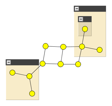
GraphML supports nested graphs, i.e., graphs in which the nodes are hierarchically ordered. The hierarchy is expressed by the structure of the GraphML document. A node in a GraphML document may have a graph element which itself contains the nodes which are in the hierarchy below this node. Here is an example for a nested graph and the corresponding GraphML document. Note that in the drawing of the graph the hierarchy is expressed by containment, i.e., the a node a is below a node b in the hierarchy if and only if the graphical representation of a is entirely inside the graphical representation of b.
The file nested.graphml shows the corresponding GraphML document:
<?xml version="1.0" encoding="UTF-8"?>
<graphml xmlns="http://graphml.graphdrawing.org/xmlns"  xmlns:xsi="http://www.w3.org/2001/XMLSchema-instance"
xsi:schemaLocation="http://graphml.graphdrawing.org/xmlns http://graphml.graphdrawing.org/xmlns/1.0/graphml.xsd">
  <graph id="G" edgedefault="undirected">
    <node id="n0"/>
    <node id="n1"/>
    <node id="n2"/>
    <node id="n3"/>
    <node id="n4"/>
    <node id="n5">
        <graph id="n5:" edgedefault="undirected">
          <node id="n5::n0"/>
          <node id="n5::n1"/>
          <node id="n5::n2"/>
          <edge id="e0" source="n5::n0" target="n5::n2"/>
          <edge id="e1" source="n5::n1" target="n5::n2"/>
        </graph>
    </node>
    <node id="n6">
        <graph id="n6:" edgedefault="undirected">
          <node id="n6::n0">
              <graph id="n6::n0:" edgedefault="undirected">
                <node id="n6::n0::n0"/>
               </graph>
          </node>
          <node id="n6::n1"/>
          <node id="n6::n2"/>
          <edge id="e10" source="n6::n1" target="n6::n0::n0"/>
          <edge id="e11" source="n6::n1" target="n6::n2"/>
        </graph>
    </node>
    <edge id="e2" source="n5::n2" target="n0"/>
    <edge id="e3" source="n0" target="n2"/>
    <edge id="e4" source="n0" target="n1"/>
    <edge id="e5" source="n1" target="n3"/>
    <edge id="e6" source="n3" target="n2"/>
    <edge id="e7" source="n2" target="n4"/>
    <edge id="e8" source="n3" target="n6::n1"/>
    <edge id="e9" source="n6::n1" target="n4"/>
  </graph>
</graphml>
The edges between two nodes in a nested graph have to be declared in a graph, which is an ancestor of both nodes in the hierarchy. Note that this is true for our example. Declaring the edge between node n6::n1 and node n4::n0::n0 inside graph n6::n0 would be wrong while declaring it in graph G would be correct. A good policy is to place the edges at the least common ancestor of the nodes in the hierarchy, or at the top level.
For applications which can not handle nested graphs the fall-back behaviour is to ignore nodes which are not contained in the top-level graph and to ignore edges which have do not have both endpoints in the top-level graph.
3.2 Hyperedges
Hyperedges are a generalization of edges in the sense that they do not only relate two endpoints to each other, they express a relation between an arbitrary number of enpoints. Hyperedges are declared by ahyperedge element in GraphML.
For each enpoint of the hyperedge, this hyperedge element contains an
endpoint element.
The endpoint element must have an XML-Attribute node, which contains the identifier of a node in the document.
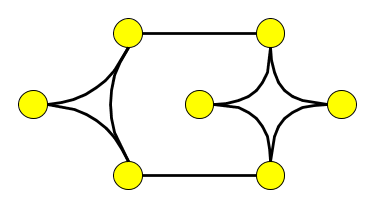
The following example contains two hyperedges and two edges.
The hyperedges are illustrated by joining arcs, the edges by straight lines.
Note that edges can be either specified by an edge element or by a hyperedge element containing two endpoint elements.
The file hyper.graphml shows the corresponding GraphML document:
<?xml version="1.0" encoding="UTF-8"?>
<graphml xmlns="http://graphml.graphdrawing.org/xmlns"  xmlns:xsi="http://www.w3.org/2001/XMLSchema-instance"
xsi:schemaLocation="http://graphml.graphdrawing.org/xmlns http://graphml.graphdrawing.org/xmlns/1.0/graphml.xsd">
  <graph id="G" edgedefault="undirected">
    <node id="n0"/>
    <node id="n1"/>
    <node id="n2"/>
    <node id="n3"/>
    <node id="n4"/>
    <node id="n5"/>
    <node id="n6"/>
    <hyperedge>
       <endpoint node="n0"/>
       <endpoint node="n1"/>
       <endpoint node="n2"/>
     </hyperedge>
    <hyperedge>
       <endpoint node="n3"/>
       <endpoint node="n4"/>
       <endpoint node="n5"/>
       <endpoint node="n6"/>
     </hyperedge>
    <hyperedge>
       <endpoint node="n1"/>
       <endpoint node="n3"/>
     </hyperedge>
    <edge source="n0" target="n4"/>
  </graph>
</graphml>
Like edges, hyperedges and enpoints may have an XML-Attribute id, which defines a unique identifier for the corresponding element.
3.3 Ports
A node may specify different logical locations for edges and hyperedges to connect. The logical locations are called "ports". As an analogy, think of the graph as a motherboard, the nodes as integrated circuits and the edges as connecting wires. Then the pins on the integrated circuits correspond to ports of a node.
The ports of a node are declared by port elements as children of the corresponding node elements. Note that port elements may be nested, i.e., they may contain port elements themselves.
Each port element must have an XML-Attribute name, which is an identifier for this port. The edge element has optional XML-Attributes sourceport and targetport with which an edge may specify the port on the source, resp. target, node.
Correspondingly, the endpoint element has an optional XML-Attribute port.
The document port.graphml is an example for a document with ports:
<?xml version="1.0" encoding="UTF-8"?>
<graphml xmlns="http://graphml.graphdrawing.org/xmlns"  xmlns:xsi="http://www.w3.org/2001/XMLSchema-instance"
xsi:schemaLocation="http://graphml.graphdrawing.org/xmlns http://graphml.graphdrawing.org/xmlns/1.0/graphml.xsd">
  <graph id="G" edgedefault="directed">
    <node id="n0">
      <port name="North"/>
      <port name="South"/>
      <port name="East"/>
      <port name="West"/>
    </node>
    <node id="n1">
      <port name="North"/>
      <port name="South"/>
      <port name="East"/>
      <port name="West"/>
    </node>
    <node id="n2">
      <port name="NorthWest"/>
      <port name="SouthEast"/>
    </node>
    <node id="n3">
      <port name="NorthEast"/>
      <port name="SouthWest"/>
    </node>
    <edge source="n0" target="n3" sourceport="North" targetport="NorthEast"/>
    <hyperedge>
       <endpoint node="n0" port="North"/>
       <endpoint node="n1" port="East"/>
       <endpoint node="n2" port="SouthEast"/>
     </hyperedge>
  </graph>
</graphml>